TGT Indicator...
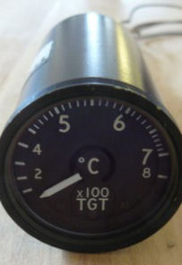
The Turbine Gas Temperature or TGT gauge is the main engine temperature gauge and a primary indicator of engine health.
My instrument is driven by a small dc voltage and is therefore very easy to control from an Arduino PWM pin.
The Turbine Gas Temperature or TGT gauge is the main engine temperature gauge and a primary indicator of engine health.
My instrument is driven by a small dc voltage and is therefore very easy to control from an Arduino PWM pin.
My TGT gauge is nothing more than a simple moving coil meter. In an actual aircraft the operating current would be provided by a thermocouple mounted in the engine gas flow and that’s what I needed to simulate.
The input to the gauge is taken from an Arduino PWM pin, through a current limiting/adjustment resistor, with the other side of the gauge being connected to the Arduino ground, as shown in the circuit diagram below. Note that a limiting resistor is essential – these gauges work with inputs of 10′s of millivolts and applying 5V directly will give you a seriously bent pointer!
Resistor values were determined by initially connecting a large value (100K) potentiometer in series with the gauge, adjusting it slowly downwards until the gauge showed full scale deflection, and then measuring the set value with an ohmmeter. I would expect different gauges to need different value resistors, but for mine I found a 6K8 series resistor brought the adjustment roughly midway across a 1K potentiometer. I chose a multi-turn potentiometer to enable finer adjustment.
An unexpected bonus was the gauge is perfectly linear, despite the Hawk’s logarithmic TGT scale – if you set a PWM value of 255 to be 800 degrees, then a value of 128 is 400. And 0 is also zero, unlike the fuel gauge! This makes calculating the PWM drive value very simple.
The Arduino sketch I used to test the TGT gauge is provided in the listing below. Test values to display are entered via the Arduino IDE serial terminal.
//tgt gauge driver
// This code was written to test the tgt gauge in isolation. The desired temperature (normally received from fsx) is entered by the user on the arduino ide serial terminal.
static float fsxTgt = 0; // tgt received from FSX, for testing purposes emulated by entering a value on serial terminal
static int tgtPwm = 0; // tgt pwm value (0 - 255)
const int tgtPin = 5; // tgt gauge connected to Arduino pin 5
void setup()
{
pinMode(tgtPin, OUTPUT); // configure tgt gauge pin as an output
Serial.begin(9600); // setup serial communication
Serial.println("Enter tgt 0 - 800 degrees C?"); // prompt user for a tgt value
}
void loop()
{
if (Serial.available()) // check if any serial input received and if so then...
{
fsxTgt = Serial.parseFloat(); // get serial input as a floating point number
fsxTgt = constrain(fsxTgt, 0, 900); // limit the entered temperature to a value between 0 and 900 degrees C
}
tgtPwm = int(fsxTgt*0.25); //calculate pwm value for temperature to indicate, i.e. multiply by scaling factor
analogWrite(tgtPin,tgtPwm); //write pwm value to tgt gauge
}
This test sketch is available for download from Github.
Although the TGT gauge is working, having seen from my DGI stepper motor experiments how much stress 500 Hz PWM puts on a component, I'll modify the circuit before installation by incorporating a smoothing capacitor across the meter coil.