The driver code is best viewed on Github, though included here for completeness. It sets a custom PWM frequency to simulate points of a sinewave.
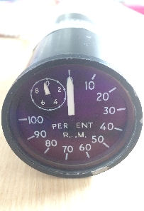
// This code was written to test the %rpm gauge in isolation. The desired %rpm (normally received from fsx) is entered by the user on the arduino ide serial terminal.
// sinewave generator is based on the "DDS-sinewave - 3phase" code described in the paper Design Strategy for a 3-Phase Variable Frequency Drive, O D Munoz, California Polytechnic State University, 2011.
#include "avr/pgmspace.h"
#include "avr/io.h"
// table of 256 sinewave values (one sine period) stored in flash memory
PROGMEM const unsigned char sine256[] =
{
127,130,133,136,139,143,146,149,152,155,158,161,164,167,170,173,176,178,181,184,187,190,192,195,198,200,203,205,208,210,
212,215,217,219,221,223,225,227,229,231,233,234,236,238,239,240,242,243,244,245,247,248,249,249,250,251,252,252,253,253,
253,254,254,254,254,254,254,254,253,253,253,252,252,251,250,249,249,248,247,245,244,243,242,240,239,238,236,234,233,231,
229,227,225,223,221,219,217,215,212,210,208,205,203,200,198,195,192,190,187,184,181,178,176,173,170,167,164,161,158,155,
152,149,146,143,139,136,133,130,127,124,121,118,115,111,108,105,102,99,96,93,90,87,84,81,78,76,73,70,67,64,62,59,56,54,51,
49,46,44,42,39,37,35,33,31,29,27,25,23,21,20,18,16,15,14,12,11,10,9,7,6,5,5,4,3,2,2,1,1,1,0,0,0,0,0,0,0,1,1,1,2,2,3,4,5,
5,6,7,9,10,11,12,14,15,16,18,20,21,23,25,27,29,31,33,35,37,39,42,44,46,49,51,54,56,59,62,64,67,70,73,76,78,81,84,87,
90,93,96,99,102,105,108,111,115,118,121,124
};
#define cbi(sfr, bit) (_SFR_BYTE(sfr) &= ~_BV(bit))
#define sbi(sfr, bit) (_SFR_BYTE(sfr) |= _BV(bit))
#define PWM_OUT_1 11 // PWM output for phase 1 on pin 11
#define PWM_OUT_2 10 // PWM output for phase 2 on pin 10
#define PWM_OUT_3 9 // PWM output for phase 3 on pin 9
#define OFFSET_1 85 // array offset for second-phase (+120 degrees)
#define OFFSET_2 170 // array offset for third-phase (+240 degrees)
static float fsxRpm = 0; // rpm (%) received from FSX, for testing purposes emulated by entering a value on serial terminal
const double refclk = 31250.0; // assumed as approximately 31250.0 and then tweaked to calibrate gauge indication
const uint64_t twoTo32 = pow(2, 32); // compute value at startup and use as constant
// variables used inside interrupt service declared as volatile
volatile uint8_t icnt; // var inside interrupt
volatile uint8_t icnt1; // var inside interrupt
volatile uint8_t c4ms; // counter incremented every 4ms
volatile uint32_t phase_accum; // phase accumulator
volatile uint32_t tword_m; // tuning word m
//************************************
void setup()
{
Serial.begin(9600); // setup serial communication
Serial.println("Enter %rpm"); // prompt user for a %rpm value
pinMode(PWM_OUT_1, OUTPUT); // configure phase 1 pin as PWM output
pinMode(PWM_OUT_2, OUTPUT); // configure phase 2 pin as PWM output
pinMode(PWM_OUT_3, OUTPUT); // configure phase 3 pin as PWM output
// Setup the timers
setup_timer1();
setup_timer2();
// disable interrupts to avoid timing distortion
cbi (TIMSK0, TOIE0); // disable Timer0, note delay() function is now not available
sbi (TIMSK2, TOIE2); // enable Timer2 Interrupt
tword_m=twoTo32*fsxRpm/refclk; // calculate new tuning word
}
//************************************
void loop()
{
if (c4ms > 250) // timer - wait for a full second
{
c4ms = 0;
if (Serial.available()) // check if any serial input received and if so then...
{
fsxRpm = Serial.parseFloat(); // get serial input as a floating point number
fsxRpm = constrain(fsxRpm,0,110); // limit the entered %rpm to a value between 0 and 110% which will limit output frequency from 0 to 77 Hz
fsxRpm = fsxRpm*0.7; // convert %rpm to PWM frequency (0.7 Hz per 1%, e.g. 10% = 7 Hz, 100% = 70 Hz)
}
cbi (TIMSK2, TOIE2); // disable Timer2 Interrupt
tword_m=twoTo32*fsxRpm/refclk; // calulate new tuning word
sbi (TIMSK2, TOIE2); // enable Timer2 Interrupt
}
}
//************************************
// timer1 setup
// set prescaler to 1, PWM mode to phase correct PWM, clock = 16000000/512 = 31.25kHz
void setup_timer1(void)
{
// Timer1 Clock Prescaler to 1
sbi (TCCR1B, CS10);
cbi (TCCR1B, CS11);
cbi (TCCR1B, CS12);
// Timer0 PWM Mode set to Phase Correct PWM
cbi (TCCR1A, COM1A0); // clear Compare Match
sbi (TCCR1A, COM1A1);
cbi (TCCR1A, COM1B0); // clear Compare Match
sbi (TCCR1A, COM1B1);
sbi (TCCR1A, WGM10); // Mode 1, Phase Correct PWM
cbi (TCCR1A, WGM11);
cbi (TCCR1B, WGM12);
cbi (TCCR1B, WGM13);
}
//*************************************
// timer2 setup
// set prescaler to 1, PWM mode to phase correct PWM, clock = 16000000/512 = 31.25kHz
void setup_timer2(void)
{
// Timer2 Clock Prescaler to 1
sbi (TCCR2B, CS20);
cbi (TCCR2B, CS21);
cbi (TCCR2B, CS22);
// Timer2 PWM Mode set to Phase Correct PWM
cbi (TCCR2A, COM2A0); // clear Compare Match
sbi (TCCR2A, COM2A1);
sbi (TCCR2A, WGM20); // Mode 1, Phase Correct PWM
cbi (TCCR2A, WGM21);
cbi (TCCR2B, WGM22);
}
//**************************************
// Timer2 Interrupt Service at 31.25kHz = 32us, this is the timebase REFCLOCK for the generator
// FOUT = (M (REFCLK)) / (2 exp 32) giving a runtime of 8 microseconds (inclusive of push and pop)
ISR(TIMER2_OVF_vect)
{
phase_accum += tword_m; // phase accumulator with 32 bits
icnt = phase_accum >> 24; // use upper 8 bits as frequency information
OCR2A = pgm_read_byte_near(sine256 + icnt); // read phase 1 value from ROM sine table and send to PWM DAC
OCR1A = pgm_read_byte_near(sine256 + (uint8_t)(icnt + OFFSET_1)); // read phase 2 value from ROM sine table and send to PWM DAC
OCR1B = pgm_read_byte_near(sine256 + (uint8_t)(icnt + OFFSET_2)); // read phase 3 value from ROM sine table and send to PWM DAC
if (icnt1++ == 125) // increment variable c4ms every 4 milliseconds
{
c4ms++;
icnt1 = 0;
}
}