Fuel Contents Gauge...
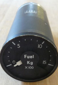
The Fuel Contents gauge provides an indication of fuel remaing in Kg.
My instrument is driven by a small dc voltage and is therefore very easy to control from an Arduino PWM pin.
The Fuel Contents gauge provides an indication of fuel remaing in Kg.
My instrument is driven by a small dc voltage and is therefore very easy to control from an Arduino PWM pin.
My Fuel gauge is not a genuine Hawk instrument and is more likely a Smiths Industries made simulator instrument for some other aircraft type. The gauge originally had two separate left and right pointers (each with its own moving coil) so I removed the rear assembly leaving only one in place, and repainted the remaining pointer plain white. I also took the opportunity to add correct labeling with white Letraset (Fuel Kg).
The instrument is a simple moving coil meter. In an actual aircraft the operating current would be provided from the amplified signal of a fuel level sensor and that’s what I needed to simulate.
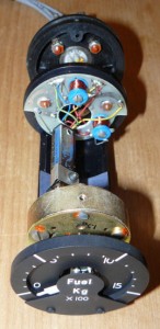
The input to the gauge is taken from an Arduino PWM pin, through a variable resistor to set sensitivity, with the other side of the gauge being connected to the Arduino ground, as shown below. Since the sensitivity of my fuel gauge is much less than the TGT gauge the series resistor used in the TGT interface is not required. I mounted the variable resistor with a small nut and bolt through a mounting hole of the removed meter coil.
To set sensitivity I drove the Arduino pin to maximum (PWM value 255) and wound the potentiometer slowly upwards until the gauge indicated full scale deflection. No doubt different gauges will need different value resistors, but for mine I found the adjustment was roughly midway across a 1K potentiometer. I chose a multi-turn potentiometer to enable finer adjustment.
My gauge originally had an inductor connected in parallel across each meter coil, however I removed this as I found it impacted greatly on sensitivity and severely limited the usable PWM range of the Arduino pin. The range is already restricted in any case, since 0 on a fuel gauge is not zero input, as it is for example on the TGT gauge. This is of course fairly obvious, since most fuel gauges show empty with some fuel remaining.
The driver code needs to calculate the PWM value for a given value to display and then add an offset. This can be seen in the test sketch listing below. Test values to display are entered via the Arduino IDE serial terminal.
//fuel contents gauge driver
// This code was written to test the fuel gauge in isolation. The desired fuel quantity (normally received from fsx) is entered by the user on the arduino ide serial terminal.
static float fsxFuel = 0; // fuel quantity (Kg) received from FSX, for testing purposes emulated by entering a value on serial terminal
static int fuelPwm = 0; // fuel quantity pwm value (0 - 255)
const int fuelPin = 3; // fuel gauge connected to Arduino pin 3
void setup()
{
pinMode(fuelPin, OUTPUT); // configure fuel gauge pin as an output
Serial.begin(9600); // setup serial communication
Serial.println("Enter fuel quantity 0 - 1500 Kg?"); // prompt user for a fuel quantity value
}
void loop()
{
if (Serial.available()) // check if any serial input received and if so then...
{
fsxFuel = Serial.parseFloat(); // get serial input as a floating point number
fsxFuel = constrain(fsxFuel, 0, 1500); // limit the entered fuel quantity to a value between 0 and 1500 Kg
}
fuelPwm = int(fsxFuel*0.1157+72.596); //calculate pwm value for fuel quantity to indicate, i.e. multiply by scaling factor and add offset to empty
analogWrite(fuelPin,fuelPwm); //write pwm value to fuel gauge
}
This test sketch is available for download from Github.
Although the fuel gauge is working, having seen from my DGI stepper motor experiments how much stress 500 Hz PWM puts on a component, I'll modify the circuit before installation by incorporating a smoothing capacitor across the meter coil.